GNSS and INS performance accuracy is generally tested in an ideal static environment, and often not representative of end use performance. Dynamic environments introduce error sources such as multipath, obscured sky view, vibration, inconsistent RTK data streams and more.
 3DMGQ7-GNSS/INS Dynamic Performance Test Report
Article from | Parker LORD Microstrain Sensing
Test Setup


GQ7 Configuration
The GQ7 was set up with a standard configuration that would perform well in a variety of dynamic environments.
Heading Initialization
Heading was set to initialize from dual antenna heading or GNSS kinematic alignment, whichever source was available first. Dual antenna heading is the most robust initialization source, but takes time and a clear view of the sky for an accurate measurement. In a wheeled vehicle, GNSS kinematic alignment is a valid initialization method and allows for rapid filter initialization.
Filter Aiding Measurements
• GNSS position and velocity: Default filter aiding source, required for navigation
• Dual antenna heading: Dual antenna heading measurements are not critical for maintaining accurate heading in dynamic environments. During periods of consistent linear acceleration and GNSS data, the EKF will converge on an accurate estimate of heading. However, in periods of low dynamics, heading stability is solely dependent on gyro integration, which will drift over time. Dual antenna heading provides stability during these periods.

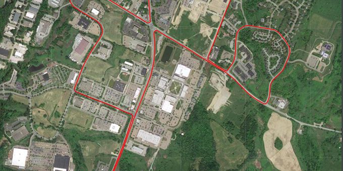
Test Environment
GNSS and INS performance accuracy is generally tested in an ideal static environment, and often not representative of end use performance. Dynamic environments introduce error sources such as multipath, obscured sky view, vibration, inconsistent RTK data streams and more. This test was conducted in an standard urban environment, including dense tree coverage, underpasses, buildings and imperfect cellular data coverage.
Results
A reference navigation solution was generated using a higher grade INS and post-processing software. In order to have more representative data, the initial EKF convergence period was removed from the results. In addition, position accuracy is reported in the test vehicle reference frame and not the NED frame. This removes any error due to the vehicle frame lever arm offset between the 3DMGQ7 and the reference system.


The content & opinions in this article are the author’s and do not necessarily represent the views of RoboticsTomorrow

Parker LORD – MicroStrain Sensing Products
Parker LORD - MicroStrain Inertial Sensing Products manufactures the smallest and lightest industrial-grade inertial sensors available that are used in advanced manufacturing, off-highway vehicles, commercial and military manned and unmanned vehicles, and civil structures. Products come temperature compensated using a proprietary calibration process and include inclinometers, vertical reference units, IMUs, AHRS and INS/GPS for navigation, stabilization, mobile mapping, terrain compensation and more. Contact LORD for additional custom designed solutions.
Other Articles
Ways to Improve Your IMU Performance
Powering Drones with Improved Mobile Mapping Systems
High Performance Inertial Sensors for Robotic Systems
More about Parker LORD – MicroStrain Sensing Products
Comments (0)
This post does not have any comments. Be the first to leave a comment below.
Featured Product